In today’s mobile age , our cell phones keep us connected to everyone 24×7. Without mobiles, we’ll all be back to the Stone Age. But irrespective of their class, they all run on a battery which goes down at the end of the day. The smarter your phone, the sooner it runs out of charge.

Have you ever wondered about the one thing that keeps your phones going? Yes, we are talking about your cell phone chargers here. Cellphone chargers are nothing by simple AC to DC converters, i.e. they take the regular AC supply of 220/120 volts coming to our homes, and give a constant DC output voltage of around 5 V (approx). In this article, we are going to talk about the internals of a cellphone charger and even create a working circuit.
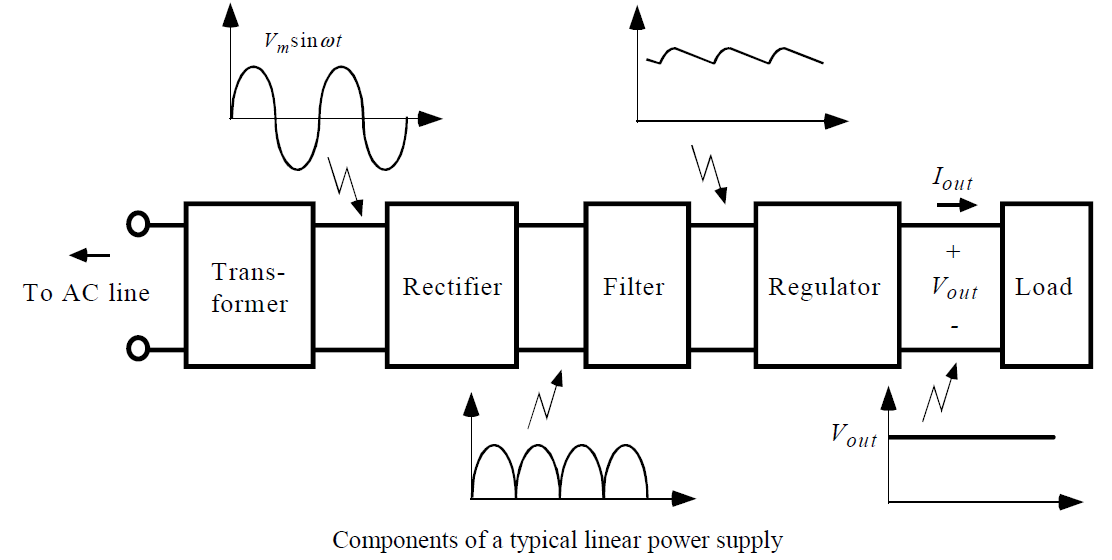
The cellphone charger extracts the power from the home supply (AC 220V) and converts it to a DC level of required voltage. The voltage output is fairly constant which means it is regulated. The output voltage remains constant whether the load current changes or there are fluctuations in the input AC voltage. This is achieved in a series of steps:
Step 1: Step down the high input of 220V to a working output voltage. This is achieved with the help of a transformer
Step 2: Convert AC signal into a DC signal using rectification
Step 3: Smoothen the output of the rectifier by filtering the ripples from DC rectification
Step 4: Generate a steady output signal with the help of a regulator
The circuit below gives a high level view of the working of a “regulated power supply”.
The components used are very common and simple. Most of you know what goes on inside of them.
Transformer:
The transformer contains two huge copper coils, one between the two terminals of the input power supply and other between the two terminals of the output. Here we use a step-down transformer which means it will convert high voltage to low voltage. The number of turns of the coil inside will determine the voltage supported at input and output both.
i.e. Vin/Vout=Nin/Nout
Vin = Input AC voltage
Vout = Output AC voltage
Nin = Number of turns at the input terminal of transformer
Nout = Number of turns at the output terminal of transformer
Rectifier:
Now comes the rectifier part. This converts the AC voltage output of the transformer to a DC voltage. It just reverses the polarity of one half of the period of the AC signal. This will make both parts have the same polarity. Here we use a full wave bridge rectifier to convert the AC signal to DC.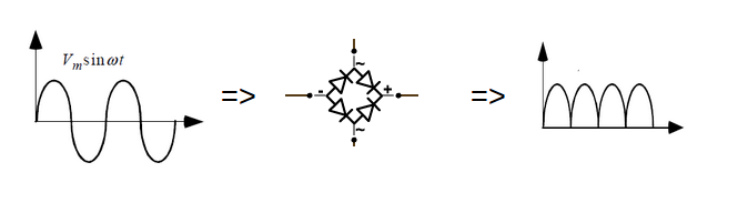
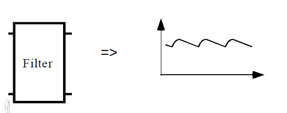
Filter:
The output from the rectification stage is DC, but hardly constant. So, we use capacitive filtering to smoothen the output. In this example, using a simple low pass filter at the output of the rectifier, however in real life, higher order filters may be used, which would give a much more smoother output.
Regulator:
The filtering significantly smoothens the output, but even after that small ripples remain. If we use this directly to charge our phones, the constant fluctuation in the voltage may damage the device. It is very important to have a steady output voltage with minimal fluctuations. This is where the regulator stage kicks in.
Here we have used a simple zener diode based regulator. The tendency of a zener diode is to have a fixed voltage between its two terminals when reversed biased. So when input voltage changes, the current through the zener diode also changes inversely so that the output is constant. This regulator is quite simple to create, but its is that it wastes a lot of power. So, the cell phone chargers typically use IC voltage regulators, such as IC 7805, IC 7806, IC 7812 etc.
Combining all the steps explained below, here’s a working circuit for “regulated power supply”. You can even go ahead and run it with DoCircuits and see it working for yourself !!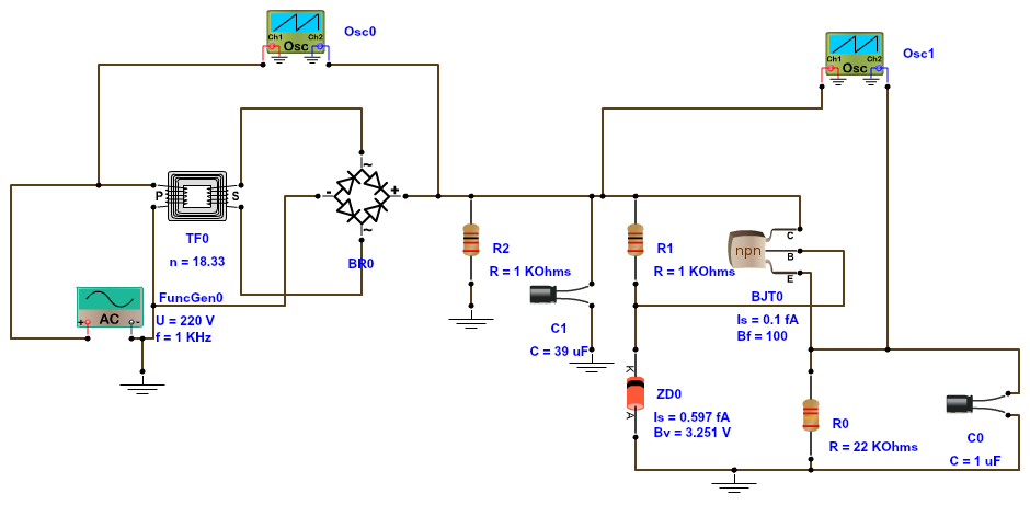
All the symbols have their usual meanings. Function generator is used as a power input source to the system. OSC1 and OSC2 are the CRO’s placed at the input and at the output terminals and can be used to study the changes between them.
So, hope you will now appreciate the small charging device at your home a little better, and if it breaks down, don’t hesitate to open it up and pry upon the internals. Even if you want some unique voltage supply, you can custom build it so easily now. But like any other technology, people are revolutionizing this as well. We’ll leave you with a glimpse of the same:
Please do share your comments and feedback
No comments:
Post a Comment